GeeKee CeeBee
Welcome to GeeKee CeeBee's Page: House of Mechatronics Projects & Lessons.
Contact Email: Ceebee1108@gmail.com
Follow me on Youtube
__________________________________________________________________________________________________________________________________
PID DC Motor Position Control
Components List
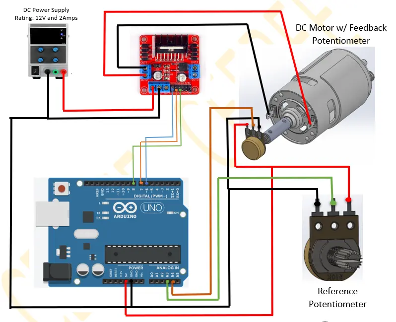
Arduino Uno (Affiliate Link)
DC Motor Double-ended Shaft (BestTong 775)
L298N Dual H-bridge Motor Driver (Affiliate Link)
2X Rotary Potentiometer (Affiliate Link)
Shaft Coupler (Custom)
DC Power Supply (6-12V)(Affiliate Link)
Jumper Wires and Breadboard (Affiliate Link)
Step-by-step video guide
Control Diagram

Wiring Diagram
__________________________________________________________________________________________________________________________________
Arduino Code
//GeeKee CeeBee
// ************ DEFINITIONS************

int potPin = A3;          // Reference Potentiometer
int encoder_pot = A2;    // Position Feedback sensor

int val = 0;
int encoder_val =0;
float kp = 0.2;
float ki = 0.00000 ;
float kd = 2.00;
float Theta, Theta_d;
int dt;
unsigned long t;
unsigned long t_prev = 0;
int val_prev =0;
float e, e_prev = 0, inte, inte_prev = 0;
float Vmax = 12;
float Vmin = -12;
float V = 0.1;
const byte PWMPin = 6;
const byte DirPin1 = 7;
const byte DirPin2 = 8;


//***Motor Driver Functions*****

void WriteDriverVoltage(float V, float Vmax) {
  int PWMval = int(255 * abs(V) / Vmax);
  if (PWMval > 255) {
    PWMval = 255;
  }
  if (V > 0) {
    digitalWrite(DirPin1, HIGH);
    digitalWrite(DirPin2, LOW);
  }
  else if (V < 0) {
    digitalWrite(DirPin1, LOW);
    digitalWrite(DirPin2, HIGH);
  }
  else {
    digitalWrite(DirPin1, LOW);
    digitalWrite(DirPin2, LOW);
  }
  analogWrite(PWMPin, PWMval);

}


void setup() {
  Serial.begin(9600);
  pinMode(DirPin1, OUTPUT);
  pinMode(DirPin2, OUTPUT);

}


void loop() {
  val = analogRead(potPin);                           // Read V_out from Reference Pot
  encoder_val =analogRead(encoder_pot);               // Read V_out from Feedback Pot
  t = millis();
  dt = (t - t_prev);                                  // Time step
  Theta = val;                                        // Theta= Actual Angular Position of the Motor
  Theta_d = encoder_val;                              // Theta_d= Desired Angular Position of the Motor

  e = Theta_d - Theta;                                // Error
  inte = inte_prev + (dt * (e + e_prev) / 2);         // Integration of Error
  V = kp * e + ki * inte + (kd * (e - e_prev) / dt) ; // Controlling Function

  if (V > Vmax) {
      V = Vmax;
      inte = inte_prev;
    }
    if (V < Vmin) {
      V = Vmin;
      inte = inte_prev;
      val_prev= val;
    }
  WriteDriverVoltage(V, Vmax);
  Serial.println(Theta_d); Serial.print(" \t");
    Serial.print(Theta); Serial.print(" \t ");
   t_prev = t;
    inte_prev = inte;
    e_prev = e;
    delay(10);

}